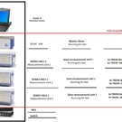
LRI-AAST: L1 and L2 laboratory DACS systems
| Lab | Equipment |
|---|---|
| L1 - DYNO and CORE test cells L2 - PROP1 and PROP2 test cells |
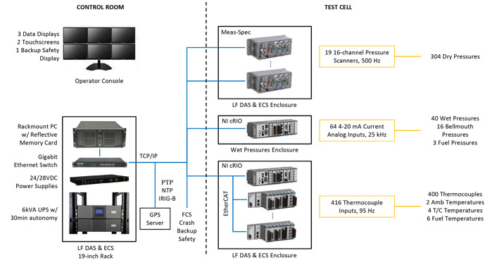
Data Acquisiton System The test cells are equipped with large DAS that can be grouped together for more channels if necessary |
| Measurement | No | Range | Notes |
|---|---|---|---|
| Fuel Flow* | 2 | 0-800 pph | To be installed on facility piping. From fuel tank to engine FMU. Redundant turbine flowmeters. The flowmeters should be volumetric; the mass calculation must be done in the LF system real time calculation. |
| Fuel Flow* | 2 | 0-2500 pph | To be installed on facility piping. Motive Flow From FMU recirculating. Redundant turbine flowmeters. The flowmeters should be volumetric; the mass calculation must be done in the LF system real time calculation. |
| Fuel Flow* | 1 | 0-1 kg/dm3 | Densimeter on facility piping for gr from volume to mass |
| Fuel Flow* | 1 | 0-800 pph | Coriolis fuel flowmeter to be used for check consistency. |
| Fuel Pressures* | 3 | 0 - 70 psig | From facility tank to FMU and motive flow from FMU to recirculation. |
| Fuel temperature* | 6 | Ambient Temperature | To be installed on facility piping near each flowmeter and before FMU |
| Time (GPS Synchronization system) |
1 | N/A | Needed to synchronize all systems. At least 1O H z is required. |
| lnlet Temperature | 4 | Ambient Temperature | To be installed on test cell inlet |
| Test Cell Pressures | 4 | Ambient Pressure | Front/Rear test cell pressure. Probes to be included. |
| Test Cell Temperatures | 4 | Ambient Temperature | Front/Rear test cell temperatures. Probes to be included. |
| Engine Torque (Dyno Test Cell) |
1 | Lb*ft | lnline torquemeter |
| Environment | 1 | Ambient Humidity, Temperature, Pressure |
Weather station to be installed outside test cell. |
| Test Cell lnlet Temperature | 4 | Ambient Temperature |
4 RTDs on test cell inlet |
| Airflow | 1 | Engine lnlet Airflow, Dyno Test Cell | Ref. dyno test cell RFQ and below notes about standard instrumentation. |
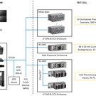
| Measurement | Type of sensor | Minimum Number of Channels |
|---|---|---|
| Temperature | Thermocouples | 180 Type E 180 Type K 40 Type T Total: 400 |
| Pressure | Pressure Scanner (see below for proposed ranges) | 300 |
| Pressure | Transducers (individual 28VDC power supplies shall be provided, see below for proposed range) | 40 |
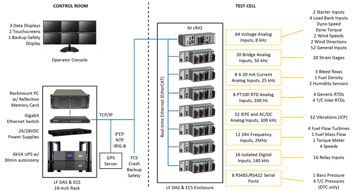
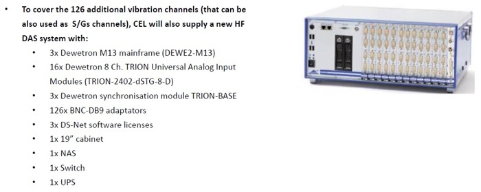
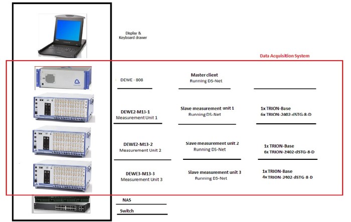
| Vibrations | ICP Accelerometers (low noise cable) | 32 |
| Clearance | Acquired on average and min signal in Vdc | 15 |
| On/off | Relays (I/O) | 16 |
| General inputs | Vdc/4-20 mA | 64 |
| Speed | Generic frequency | 8 |
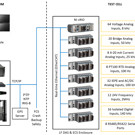
| FTS | Reflective Memory, fiber optics interface | n/a |
| Control Systems inputs | RS232, Ethernet. Facility control system, Dyno control system. | n/a |
| Force | Static Strain Gage | 20 per site |
| Temperature | Generic RTDs | 4 |
| Air Flow | Orifice or equivalent | 3 bleeds |
| Starter | Voltage and Amperes value to be acquired from the starter power generator | 2 |